The Y Service 1939-1945
The Golden Arrow Group
1944 to 1945
The Royal Signals Wireless Station Golden Arrow was a virtually mobile adaptation of the normal type of small fixed commercial radio telegraph station and while providing the traffic handling capacity of such a station is fully mobile and be set up or dismantled in three to four hours.
The complexity and bulk of the station necessarily restricted its use to the main arteries of communication such as those between Army HQ and GHQ or between a mobile GHQ overseas and a fixed station in the UK. Fortunately it is only on such a main artery that the amount of traffic rises to figures that cannot be disposed of without resource to automatic working. The Golden Arrow and its crew of 22 are completely self contained and carry its own collapsible mast gear spare valves power supply and administrative stores. The cook with his portable petrol cooker is naturally a most important member of his little community.
As far as possible the equipment was rendered capable of operating in any climate from subarctic to tropical. This has already proved of great value as sets were in service in places as far apart as Italy and Bengal.
The first Golden Arrow in Sicily went ashore late one evening from landing craft. By 09.00Hours next morning it was hard at work carrying messages to and from the War Office 1,200 miles away in the UK. The erection of a fixed station of this type involving the design and erection of a number of buildings would under peace time conditions take six to twelve months.
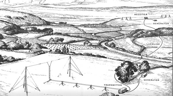
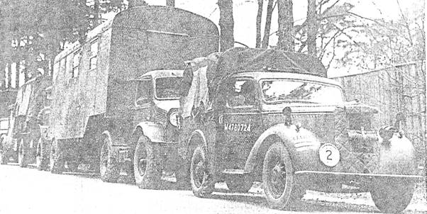
Layout of Golden Arrow Station
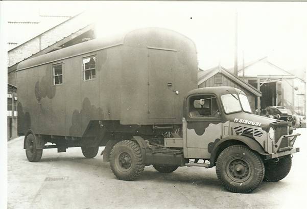
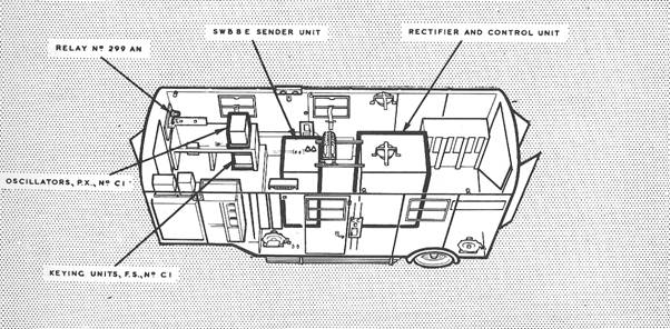
Transmitter Vehicle
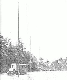
The transmitter itself is carried in a large semi articulated vehicle and is of about 3kw aerial rating. The transmitter is on the left when entering the side door and spares coils are stored in a rack against the near side wall. The anodes of the high power valves are cooled by a blast of air from a blower. Facing the transmitter is the cubicle which contains the main transformers and mercury vapour rectifiers for supplying power and the overload and time delay relays which protect the transmitter from damage due to faults or incorrect operation. Behind the power supply cubicle there is a special resilient stowage for the carriage of spare power valves. The aerial gear is all carried in or on the vehicle (the mast sections are slung below the trailer chassis) and when erected provides two dipoles on 70 foot masts one being used for the day (high) frequency and the other for the night or lower frequency.
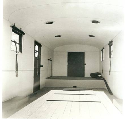
Receiving Vehicle
The receiving vehicle is of a similar shape to the transmitter vehicle, but contains a very complicated installation as it forms the traffic office in which the majority of the crew work. The forward end of the vehicle is divided off and contains air conditioning equipment which supplies a current of cool dry air to the operating room though a duct slung below the ceiling. As the air intakes to this plant are covered with filters the interior of the vehicle is kept free of dust sand and (last but by no means least) of flies and mosquitoes. In order to assist in keeping the vehicle interior cool the skin of the vehicle and the floor is lagged with glass wool. Not only does this air conditioning pre vent the unbearable conditions otherwise inevitable in a small crowded vehicle standing in a tropical sun but the exclusion of sand reduces the wear on the delicate instrument within.
In cold climates a 3kw heating element in the air intake replaces the cooling in the compressor and the vehicle is consequently ventilated and warmed in a pleasant manner. The vehicle contains a long operating bench on the off side which carries (from right to left) two key board perforators, a receiving undulator, a Wheatstone transmitter hand key and a spare undulator. The radio receivers themselves which are high grade communication receivers are carried on resilient mountings on a shelf above the undulators together with a Recording Bridge which converts the interrupted audio frequency note from the receiver into direct current to operate the undulator. The receiving aerials are similar to those for the transmitter except that a coaxial feeder is employed between the dipole itself and the receiver.