The Y Service 1939-1945
Direction Finding
The basic function of the WOYG direction finding network was to take bearings on wireless transmissions so that the locations of the transmitting stations could be plotted.
The following paragraph gives a simple explanation of the theory behind radio direction finding.
If a radio is fitted with a loop aerial the strength of the signal received will vary with the direction in which the aerial is pointing. This effect can be used to plot the direction of the transmitting station with respect to the receiver. The signal strength will vary from maximum to minimum depending on whether the aerial is in line with or at right angles to the transmitter. Since the human ear can determine minimum strength more accurately than maximum strength the minimum or null' point was used in direction finding. In theory, if two receivers located some distance apart each take a bearing on a transmitter then the transmitter will be located at the point where the two bearings cross. This is not true in practice the null point may not be sharp enough to give a precise bearing, atmospheric conditions can affect radio waves to give false readings; all D/F operators do not have the same ability and a small inaccuracy in the bearing can give a variation of many miles in the perceived location of the transmitter. For this reason three or more stations are used to obtain the most accurate location for the transmitter. If enough bearings are taken it is possible to discount those which are obviously in error.
The stations had fixed aerials which didn't move. The same effect was achieved by a radiogoniometer which matched the signals from the aerials and enabled the null' point bearing to be read off on a graduated scale. Since for any transmission there will be two null' points' 180 degrees apart senses aerial which enable the true null' point direction to be established was incorporated in the aerial system.
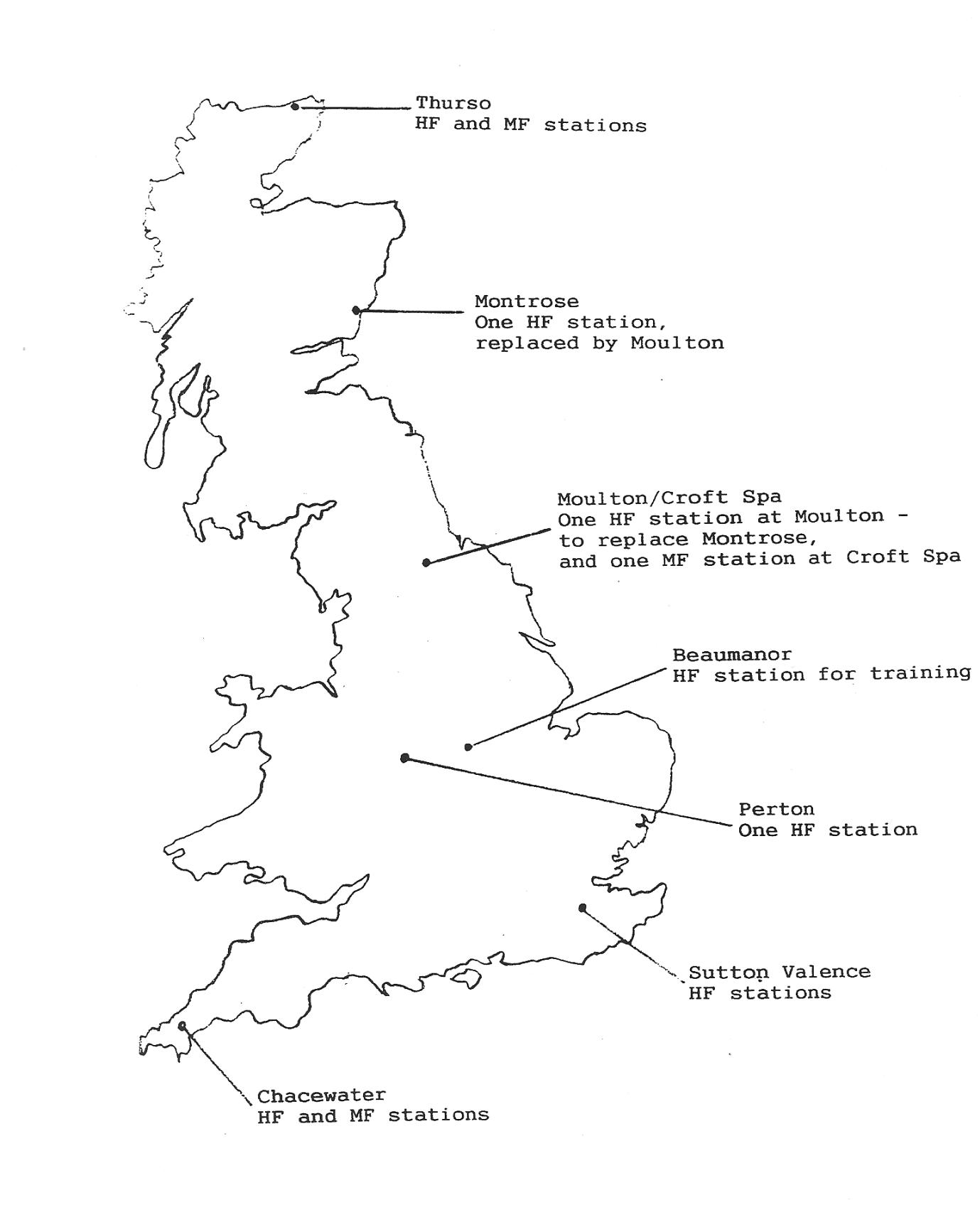
The WOYG high Frequency (H/F) fixed D/F network consisted of stations at six locations in England and Scotland. At some locations there were twin stations located a few miles apart the stations were at:
Sutton Valence near Maidstone Kent (twin stations)
Perton near Wolverhampton
Chacewater near Truro (twin Stations)
Montrose (later closed)
Moulton North Yorkshire (opened to replace Montrose)
Thurso in what was then Caithness (twin stations)
There was also Medium Frequency (M/F) stations at
Chacewater
Croft Spa a few miles from Moulton
Thurso.
A station consisted of a hut 10ft to 12ft square containing an operator's desk and chair, a radio receiver and radiogoniometer (and at Perton only, the latest development a cathode ray tube which indicated the bearing visually by a propeller shaped display) a small switchboard a supervisors desk and chair a telephone and odd items of ancillary equipment such as wavemeter etc. There would be a second hut some distance from the radio hut which would be the spare parts store and also a small shack containing a chemical toilet.
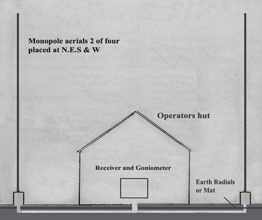
Arrangement of Fixed Antennae, D/F stations
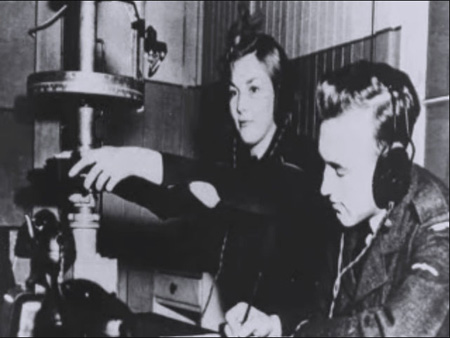
Inside an RAF D/F cabin (fixed or mobile)
Mobile D/F Units
Mobile units were with every SWS. They were issued with 15cwt vehicles or in some units 10cwt trailers
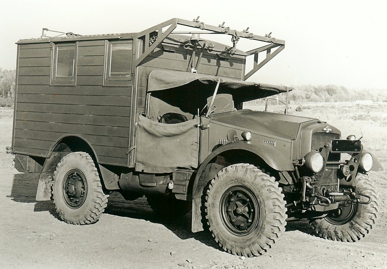
15cwt Morris D/f Unit before the Equipment was fitted
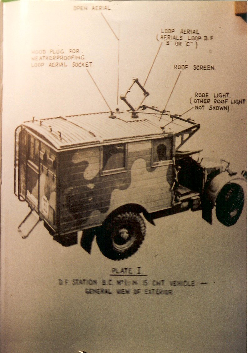
15cwt Morris D/f Unit after the Equipment was fitted
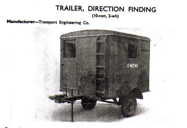
Trailer, D/F
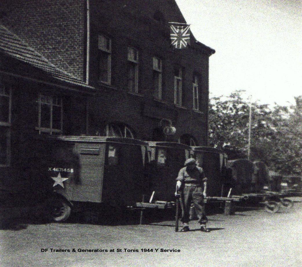
Trailers, D/F in location